CCNA Class 10: Introduction of Routed & Routing Protocols and Configuration
Introduction of Routing Protocols
Routing Fundamental
Routing is the process of forwarding data packets from their source to their destination across interconnected networks. It is a critical function in both small-local area networks (LANs) and large-scale wide-area networks (WANs), including the Internet. There are two types of data packets - Routed Protocols and Routing Protocols.
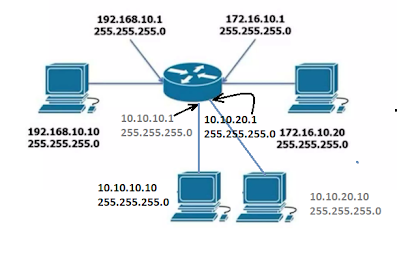
Fig: Basic Routing
Key Concepts in Routing

Router: A router is a networking device responsible for forwarding data packets between networks based on their IP addresses. It operates at the network layer (Layer 3) of the OSI model.
Routing Table: A database stored in a router that contains information about network destinations and how to reach them. Consists of:
Destination network
Next hop: The next router or device to which the packet should be sent.
Metric: A value indicating the "Cost" of reaching a destination (hop count, bandwidth, latency, reliability, load).
Interface: The router interface to use for forwarding the packet.
Packet Forwarding: When a router receives a packet, it examines the destination IP address and consults the routing table to determine the best path.
IP Addressing and Subnetting:
IP addressing helps identify devices in a network.
Subnetting divides a larger network into smaller segments to improve management and efficiency.
Routing Algorithms: These are mathematical formulas used by routing protocols to determine the best path for data packets. Examples include:
Dijkstra's Algorithm (used in OSPF)
Bellman-Ford Algorithm (used in RIP)
Static vs. Dynamic Routing:
Static Routing: Routes are manually configured and do not adapt to changes.
Dynamic Routing: Routes are automatically adjusted based on changes in the network topology.
Command: Showing the list of routing table - “show ip route”
The IP Routing Process
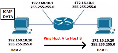
This lesson explores the packet routing process from the perspective of a router. This includes a mapping between layer 2 and layer 3 addresses, as well as the ability of the router to calculate the best path toward the destination. In verifying the configuration resulting in connectivity, we will review several commands like show ip arp, ping, and trace. The IP Routing Process is simple -
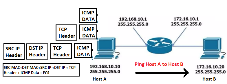
Step 01: When ping Host_A to Host_B. Internet Control Message Protocol (ICMP) creates an echo request payload. Using the TCP for reliable protocol from the transport layer, send the data to the Network layer for converting the Data to Packets.
Step 02: In this packet at Layer 3, contains the IP addresses for both the Source and Destination and request for Layer 2 and is converted with Frame. and maintain the furthermore process of the OSI model
Step 03: When arriving at the Router (Gateway), Examine the destination IP in the packet. Check its routing table for a matching route. Selects the best route based on the longest prefix match. Forward the packet to the next router or the destination network and The router forwards the ICMP packet directly to the destination device (Host B).
Step 04: ICMP Echo Reply: The target device receives the ICMP Echo Request packet.
It processes the packet and generates an ICMP Echo Reply packet.
ROUTING OVERVIEW
Routing is a process of selecting a path for forwarding data that originated from one network and is destined for a different network. Routers gather and maintain routing information to enable the transmission and receipt of such data packets. Conceptually, routing information takes the form of entries in a routing table, with one entry for each identified route. You can manually configure the entries in the routing table. Alternatively, the router can use a routing protocol to dynamically create and maintain the routing table to accommodate network changes when they occur.
A router must perform the following actions to route data:
- Identify the destination of the packet: Determine the destination network address of the packet that needs to be routed by using the subnet mask.
- Identify the sources of routing information: Determine from which sources a router can learn paths to network destinations. A source can be a directly connected interface, a dynamic routing protocol, or a statically configured route.
- Identify routes: A router may know the same route from multiple sources and choose the preferred route based on certain criteria.
- Select routes: Select the best path to the intended destination.
- Maintain and verify routing information: Update known routes and the selected route according to network conditions.

- Routers can learn the directly connected network based on the IP address and subnet mask that are configured on the local interface.
- You can manually configure network information, which is also known as a static route.
- Routers can dynamically learn destination network information by using a routing protocol that is enabled on the router.
What is the Routing Protocol?
Routing protocols are the methods and sets of rules used by routers to determine the best paths for data packets to travel across a network. They are crucial in managing communication in networks, particularly in large and dynamic environments. Routing protocols can be classified based on various criteria, such as the scope of their operation, their algorithm type, and the type of network they serve.
Types of Routing Protocols:
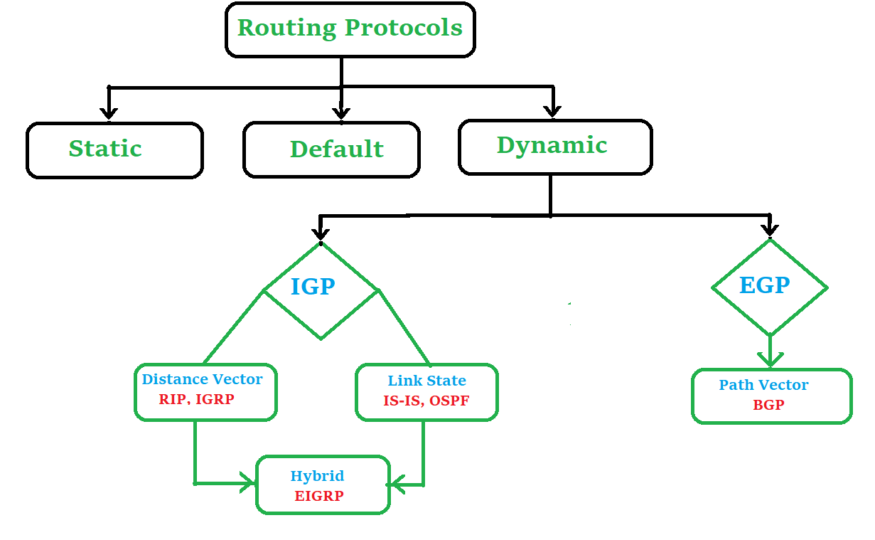
Static Routing: In static routing, the routes are manually configured by the network administrator and do not dynamically update based on network changes. This type of routing is best suited for small networks where the network topology does not change frequently.
Dynamic Routing: In dynamic routing, the routes are automatically updated based on changes in the network topology. This type of routing is best suited for large, complex networks where the network topology changes frequently. There are several types of dynamic routing protocols, including:
Distance Vector Routing Protocols: These protocols determine the best path to a destination based on distance (next hope count calculation), such as Routing Information Protocol (RIP), Routing Information Protocol v2 (RIPv2),and Interior Gateway Routing Protocol (IGRP).
Link-State Routing Protocols: These protocols maintain a map of the entire network, including information about all links and their states. Examples, Open Shortest Path First (OSPF) and Intermediate System to Intermediate System (IS-IS).
Hybrid Routing Protocols: These protocols combine features of both distance-vector and link-state protocols, such as EIGRP (Enhanced Interior Gateway Routing Protocol).
Interior Gateway Protocols (IGP): These are routing protocols used within a single autonomous system (AS), such as OSPF (Open Shortest Path First) and IS-IS (Intermediate System to Intermediate System).
Exterior Gateway Protocols (EGP): These are routing protocols used among multiple autonomous systems, such as BGP (Border Gateway Protocol)
Path Vector Routing Protocols: Example, Border Gateway Protocol (BGP).
An Autonomous System is a collection of Networks or subnets that are in the same administrative domain.
The Administrative Distance (AD) is an integer from 0 to 255. where 0 equals the most trusted route and 255 means “No traffic is allowed to be passed via this route”.
Routing metrics are configuration values used by a router to make routing decisions. The route will go in the direction of the gateway with the lowest metric.
Ex: RIP metrics is Hop count. 0 to 16 is defined as a metric number. 0 means directly connected to the network, 1 means directly connected with the router and 16 means destination unreachable. A router metric is typically based on information such as path length, bandwidth, load, hop count, path cost, delay, maximum transmission unit (MTU), reliability, and communications cost.
What is the Routed Protocol?
A routed protocol is a protocol that includes the process of carrying user information or data from one host to any other throughout the network. It operates on the network layer of the OSI model and offers logical addressing and encapsulation to the data packets. A routed protocol relies upon a routing protocol to find the best route to its destination.
Types of Routed Protocols -
IP Addresses: Internet Protocol is the most extensively used routed protocol. It has versions: IPv4, which uses 32-bit addresses, and IPv6, which uses 128-bit addresses.
IPX: Internetwork Packet Exchange is a routed protocol that is used in Novell NetWare networks. It utilizes 80-bit addresses that include a 32-bit network number and a 48-bit host number. IPX gives connectionless, dependable, and sequenced delivery of data packets.
AppleTalk: AppleTalk is a routed protocol that was utilized in Apple Macintosh networks. It makes use of 24-bit addresses that include a 16-bit network number and an 8-bit node number. AppleTalk offers connection-oriented, dependable, and sequenced transmission of data packets.
Difference Between Routing Protocol and Routed Protocol
Practice with Practical Assessment
Static Routing Architecture
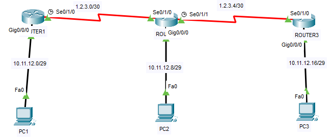
Fig: Configure the Static Routing
Step 01: Initially Routers Configuration
ROUTER1#configure terminal
Enter configuration commands, one per line. End with CNTL/Z.
ROUTER1(config)#interface gigabitEthernet 0/0/0
ROUTER1(config-if)#ip address 10.11.12.1 255.255.255.248
ROUTER1(config-if)#no shutdown
ROUTER1(config-if)#
%LINK-5-CHANGED: Interface GigabitEthernet0/0/0, changed state to up
%LINEPROTO-5-UPDOWN: Line protocol on Interface GigabitEthernet0/0/0, changed state to up
ROUTER1(config-if)#interface serial0/1/0
ROUTER1(config-if)#ip address 1.2.3.1 255.255.255.252
ROUTER1(config-if)#clock rate 64000
ROUTER1(config-if)#no shutdown
========== Router2 Configuration ===============
ROUTER2>enable
Password:
ROUTER2#configure terminal
Enter configuration commands, one per line. End with CNTL/Z.
ROUTER2(config)#interface serial 0/1/0
ROUTER2(config-if)#ip address 1.2.3.2 255.255.255.252
ROUTER2(config-if)#no shutdown
ROUTER2(config-if)#
%LINK-5-CHANGED: Interface Serial0/1/0, changed state to up
%LINEPROTO-5-UPDOWN: Line protocol on Interface Serial0/1/0, changed state to up
ROUTER2(config-if)#interface serial 0/1/1
ROUTER2(config-if)#ip address 1.2.3.5 255.255.255.252
ROUTER2(config-if)#clock rate 64000
ROUTER2(config-if)#no shutdown
%LINK-5-CHANGED: Interface Serial0/1/1, changed state to down
ROUTER2(config-if)#interface gi0/0/0
ROUTER2(config-if)#ip address 10.11.12.9 255.255.255.248
ROUTER2(config-if)#no shutdown
ROUTER2(config-if)#
%LINK-5-CHANGED: Interface GigabitEthernet0/0/0, changed state to up
%LINEPROTO-5-UPDOWN: Line protocol on Interface GigabitEthernet0/0/0, changed state to up
ROUTER2(config-if)#end
ROUTER2#
%SYS-5-CONFIG_I: Configured from console by console
ROUTER2#wr
Building configuration...
[OK]
ROUTER2#
========= Router3 Configuration ===============
Router>enable
Router#configure terminal
Enter configuration commands, one per line. End with CNTL/Z.
Router(config)#hostname ROUTER3
ROUTER3#conf t
Enter configuration commands, one per line. End with CNTL/Z.
ROUTER3(config)#interface serial0/1/0
ROUTER3(config-if)#ip address 1.2.3.6 255.255.255.252
ROUTER3(config-if)#no shutdown
ROUTER3(config-if)#
%LINK-5-CHANGED: Interface Serial0/1/0, changed state to up
%LINEPROTO-5-UPDOWN: Line protocol on Interface Serial0/1/0, changed state to up
ROUTER3(config-if)#interface gi0/0/0
ROUTER3(config-if)#ip address 10.11.12.17 255.255.255.248
ROUTER3(config-if)#no shutdown
ROUTER3(config-if)#
%LINK-5-CHANGED: Interface GigabitEthernet0/0/0, changed state to up
%LINEPROTO-5-UPDOWN: Line protocol on Interface GigabitEthernet0/0/0, changed state to up
ROUTER3(config-if)#
Step 02: All PC Configuration
PC1: IP-10.11.12.2/29, GW-10.11.12.1
PC2: IP-10.11.12.10/29, GW-10.11.12.9
PC3: IP-10.11.12.18/29, GW-10.11.12.17
Step 03: Configure the Static Routing among of the Routers
ROUTER1#show ip route
Codes: L - local, C - connected, S - static, R - RIP, M - mobile, B - BGP
D - EIGRP, EX - EIGRP external, O - OSPF, IA - OSPF inter area
N1 - OSPF NSSA external type 1, N2 - OSPF NSSA external type 2
E1 - OSPF external type 1, E2 - OSPF external type 2, E - EGP
i - IS-IS, L1 - IS-IS level-1, L2 - IS-IS level-2, ia - IS-IS inter area
* - candidate default, U - per-user static route, o - ODR
P - periodic downloaded static route
Gateway of last resort is not set
1.0.0.0/8 is variably subnetted, 2 subnets, 2 masks
C 1.2.3.0/30 is directly connected, Serial0/1/0
L 1.2.3.1/32 is directly connected, Serial0/1/0
10.0.0.0/8 is variably subnetted, 2 subnets, 2 masks
C 10.11.12.0/29 is directly connected, GigabitEthernet0/0/0
L 10.11.12.1/32 is directly connected, GigabitEthernet0/0/0
ROUTER1#configure terminal
Enter configuration commands, one per line. End with CNTL/Z.
ROUTER1(config)#ip route 10.11.12.8 255.255.255.248 1.2.3.2
ROUTER1(config)#ip route 1.2.3.4 255.255.255.252 1.2.3.2
ROUTER1(config)#ip route 10.11.12.16 255.255.255.248 1.2.3.2
ROUTER1(config)#exit
ROUTER1#
%SYS-5-CONFIG_I: Configured from console by console
ROUTER1#show ip route
Codes: L - local, C - connected, S - static, R - RIP, M - mobile, B - BGP
D - EIGRP, EX - EIGRP external, O - OSPF, IA - OSPF inter area
N1 - OSPF NSSA external type 1, N2 - OSPF NSSA external type 2
E1 - OSPF external type 1, E2 - OSPF external type 2, E - EGP
i - IS-IS, L1 - IS-IS level-1, L2 - IS-IS level-2, ia - IS-IS inter area
* - candidate default, U - per-user static route, o - ODR
P - periodic downloaded static route
Gateway of last resort is not set
1.0.0.0/8 is variably subnetted, 3 subnets, 2 masks
C 1.2.3.0/30 is directly connected, Serial0/1/0
L 1.2.3.1/32 is directly connected, Serial0/1/0
S 1.2.3.4/30 [1/0] via 1.2.3.2
10.0.0.0/8 is variably subnetted, 4 subnets, 2 masks
C 10.11.12.0/29 is directly connected, GigabitEthernet0/0/0
L 10.11.12.1/32 is directly connected, GigabitEthernet0/0/0
S 10.11.12.8/29 [1/0] via 1.2.3.2
S 10.11.12.16/29 [1/0] via 1.2.3.2
ROUTER1#
=====Router2 Static Routing Config =========
ROUTER2>enable
ROUTER2#show ip route
ROUTER2#configure terminal
Enter configuration commands, one per line. End with CNTL/Z.
ROUTER2(config)#ip route 10.11.12.0 255.255.255.248 1.2.3.1
ROUTER2(config)#ip route 10.11.12.16 255.255.255.248 1.2.3.6
ROUTER2(config)#exit
ROUTER2#
%SYS-5-CONFIG_I: Configured from console by console
ROUTER2#show ip route
S 10.11.12.0/29 [1/0] via 1.2.3.1
C 10.11.12.8/29 is directly connected, GigabitEthernet0/0/0
L 10.11.12.9/32 is directly connected, GigabitEthernet0/0/0
S 10.11.12.16/29 [1/0] via 1.2.3.6
ROUTER2#
============ Router3 Static Routing Config ===============
ROUTER3>enable
ROUTER3#conf t
Enter configuration commands, one per line. End with CNTL/Z.
ROUTER3(config)#ip route 10.11.12.0 255.255.255.248 1.2.3.5
ROUTER3(config)#ip route 10.11.12.8 255.255.255.248 1.2.3.5
ROUTER3(config)#ip route 1.2.3.0 255.255.255.252 1.2.3.5
ROUTER3(config)#exit
ROUTER3#
%SYS-5-CONFIG_I: Configured from console by console
ROUTER3#
ROUTER3#show ip route
Step 04: Test the each of the PCs by Pinging to each Other
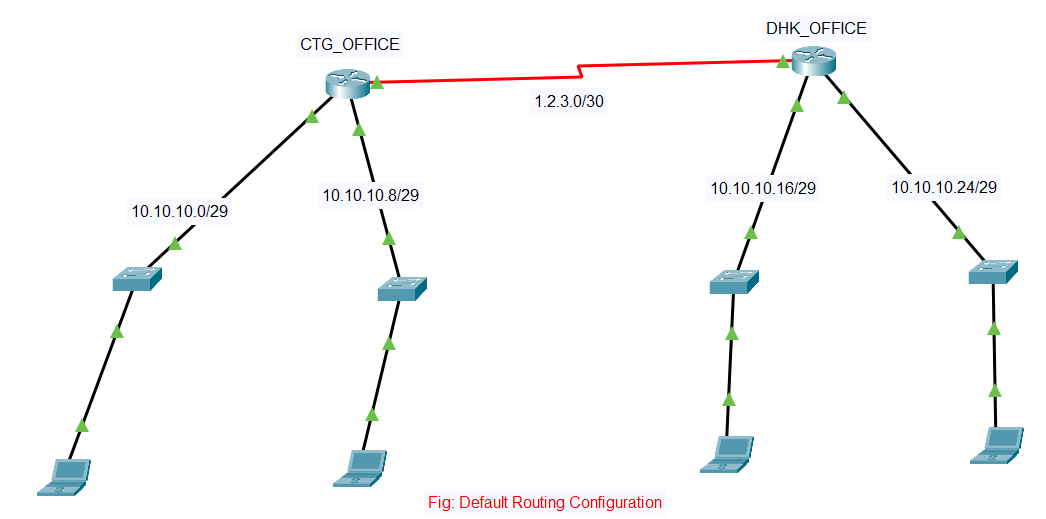
Default Routing Architecture:
Step 01: Basic Router Configuration
Hostname change for both Routers
IP Address assigned in all the Interfaces of routers.
IP Address assigned into the PCs.
Total Network design as per Diagram.
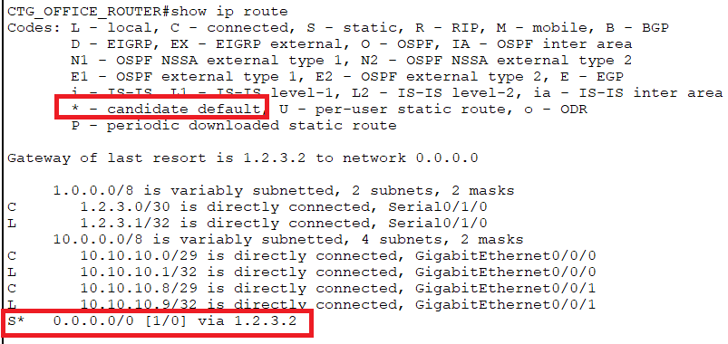
Step 02: Default Routing Configuration for both Office Router
CTG_OFFICE:
CTG_OFFICE_ROUTER#show ip route
CTG_OFFICE_ROUTER#configure terminal
CTG_OFFICE_ROUTER(config)#ip route 0.0.0.0 0.0.0.0 1.2.3.2
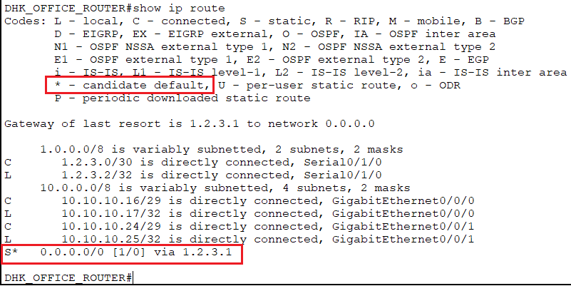
DHK_OFFICE:
DHK_OFFICE_ROUTER#show ip route
DHK_OFFICE_ROUTER#configure terminal
DHK_OFFICE_ROUTER(config)#ip route 0.0.0.0 0.0.0.0 1.2.3.1
Step 03: Ping Among the PCs for Testing.

