MTCRE-Module-01: Static Routing
OBJECTIVES- - Static Routing/Default Route
- ECMP(Equal Cost Multi-Path)
- How to force gateway over specific interface.
- Gateway reachability check and route distance.
- Routing mark and route policy.
- Recursive next-hop and scope/target-scope usages.
1. Static Routing in MikroTik RouterOS
Static routing in MikroTik means manually defining the path that packets should use to reach a destination network. It is mainly used in:
- Enterprise networks
- ISP environments
- Multi-WAN setups
- VPN routing
- Traffic engineering
- Backup internet links
MikroTik routing configuration is done mainly from: /ip route
"or"

BASIC STATIC ROUTING CONFIGURATION:
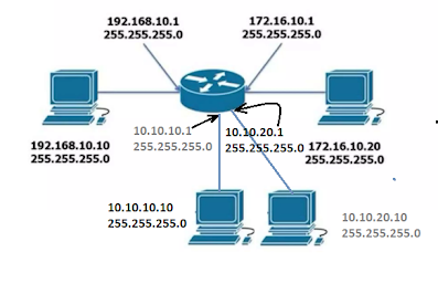
TOPOLOGY INFO -
Example for Basic Static Route (GUI/TERMINAL):
Step-01: Click on "IP" => Routes => Click on "NEW", and fill the following field for basic static/default routes=> Apply + OK.

Step-02: Ultimately, Check the Route List, Here - [A: Active, S:Static]

2. ECMP (Equal Cost Multi-Path)
To forward packets toward a single destination with the multiple paths with the equal metrics instead of selecting one single best path, its called the ECMP. Its perform basic two purposes of the entire network-
- Load Balancing for smooth distribution of the packets among the multiple paths, to ensure the best performance, high availability, and scalability of the entire network.
- Failover for continuous connection of the entire network, and ensure the minimal downtime as redundant system with the different metrics.

Example-01: The following steps of ECMP configuration for unequal WAN connection (Failover)(WAN1:WAN2=2:1) -
- Renaming MikroTik interface name
- Assigning WAN and LAN IP
- Assigning DNS IP
- NAT configuration and
- Routing configuration
- ECMP Rule in Firewall.

Fig-01: Rename the Interfaces

Fig-02: Assign the IP Addresses

Fig-03: Assign the DNS IP Address

Fig-04: NAT Configuration as masquerade.
Fig-05: Configuration the Route as Unequal WAN

Fig-06: Create the Mangle Rules per connections

Fig-07: Show the Route List
Example-02: ECMP Load Balancing and Link Redundancy Configuration.
Above network diagram can be divided into 5 steps :
- Assigning WAN and LAN IP Addresses.
- DNS Configuration.
- NAT Configuration as masquerade.
- Create Mangle Rules as per connections.
- ECMP Route Configuration.
Step-1,2, & 3 Configuration are configured as usually as per upper instructions.
Step-04: Create Mangle Rules for each WAN Connection
For Mark Connection -
Firewall => Mangle => Click (+) Sign => Chain: Input => In. Interface: ex- ether-WAN1 => action: mark connection => New Connection Mark: ex- WAN1_Conn => Uncheck: Passthrough
For Mark Routing -
Firewall => Mangle => Click (+) Sign => Chain: Output => Connection Mark: ex-WAN1_Conn => action: mark routing => New Routing Mark: ex- to_WAN1 => Uncheck: Passthrough

Step-05: Routing Table update for ECMP Configuration
IP => Routes => Click (+) Sign => General:Dst. Address -0.0.0.0/0
=> Gateway: add both wan assigned IP address => OK

IP => Routes => Click (+) Sign => General:Dst. Address -0.0.0.0/0
=> Gateway: ether1 IP address => OK & Vice versa.

Fig: Create Route

Fig: Routing List
Example-03: PBR load balancing and link redundancy configuration.

Following the below configuration step by step :
- Renaming interface name
- Assigning WAN and LAN IP
- Assigning DNS IP
- Firewall configuration and
- Routing configuration
First 3 steps will have to complete as upper given pictures instruction.
Step-04: Firewall Configuration
1. Masquerade NAT Configuration
IP > Firewall > NAT > Click (+) Sign for NEW > Chain: srcnat > action: masquerade > Apply & OK.

Address List > Click(+) Sign > Name:GroupA_Block > Address:10.10.10.0/24 > OK & Vice versa.

3. Create Mangle Rules
Mangle > Click(+) sign > General Tab > Chain: prerouting > Advanced Tab > Src. Address: GroupA_Block > Dst. Address [!]: Local_Block > Action Tab > action: mark routing > New routing mark: to_WAN1 > []: passthrough. & Vice versa
for GroupB_Block, new routing mark: to_WAN2, Example :

Step-05: Routing Configuration
Task-01:
IP > Route > Click (+) sign at General Tab > Dst. Address: 0.0.0.0/0 > Gateway: WAN1 IP > Distance: 1 > Apply & OK. Vice Versa....
Task-02:
IP > Route > Click(+) sign > Dst. Address: 0.0.0.0/0 > Gateway:WAN1_IP > Distance: 1 > Routing mark: to_WAN1 > Apply & OK. vice versa.
Example:

Testing this connection
Example-04: Load Balancing with Failover using PCC (Per Connection Classifier)
Short brief of PCC (Per Connection Classifier):
Its a load balancing technique in MikroTik routers that distributes new connections across multiple WAN/Internet links.
It works by classifying traffic based on:
- Source Address
- Destination Address
- Source Port
- Destination Port
PCC is mainly used for:
- Load Balancing multiple ISPs
- Better bandwidth utilization
- Redundancy and failover
- Session persistence
- Traffic distribution
PCC Logical Work:
per-connection-classifier=both-addresses-and-ports:X/Y
Here, X: Total number of WAN links
Y: Bucket Number
Example: both-addresses-and-ports:2/0
both-addresses-and-ports:2/1